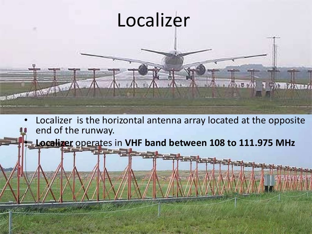


Slide 8 INNOVATIVE LOCALIZER ANTENNA INSTALLATION Thirdly Protection from Jet Blast: The new Localizer antenna would be only 53 metres from the runway starter extension. With the new Localizer antenna located closer to the sea the problem of spray dump is much greater. Sea spray had already been a cause of shutdown with the previous 8 Element Localizer antenna. Issues we faced in accomplishing this were threefold Slide 7 INNOVATIVE LOCALIZER ANTENNA INSTALLATION Secondly - Protection from Sea Spray: During Southerly Storm weather conditions a significant quantity of sea spray is dumped over and beyond the wave trap at the southern end of the runway. This restriction could impact adversely upon both the Localizer antenna element matching as well as the achieved Localizer coverage. Slide 6 INNOVATIVE LOCALIZER ANTENNA INSTALLATION Firstly - Antenna Height : Obstruction Clearance Surface requirements limited the total available height for the new Localizer antenna to no greater than one metre. There was no possibility of locating a Localizer antenna down the bank into the wave trap and so we began consideration of locating a reduced height antenna on the surface of and at the end of the RESA adjacent to the wave trap. Slide 4 INNOVATIVE LOCALIZER ANTENNA INSTALLATION Slide 5 In order to provide for a runway end safety area at the Southern end of the runway the runway strip needed to be extended over an existing roadway and up to the edge of an existing wave trap. The next photo shows the previous antenna in this configuration. This arrangement also provided protection for the antenna system from direct jet blast. The localizers associated with those ILSs had their 8 element antenna systems mounted down the bank at each end of the runway strip so as to avoid penetrating Obstruction Clearance Surfaces. Slide 2 INNOVATIVE LOCALIZER ANTENNA INSTALLATION Slide 3 Inline ILS systems serving both approaches were first installed some 30 years ago. The next photograph illustrates this layout. The south end of the runway finishes adjacent to the open sea of Cooks Strait whilst the Northern end finishes adjacent to Wellington harbour. All Rights Reserved.INNOVATIVE LOCALIZER ANTENNA INSTALLATION Wellington International Airport runway is built on a narrow neck of land. HOME ABOUT GUARANTEE TECHNICAL TECHSUPPORT CLIENTELE DISTRIBUTORS CAREERS FEEDBACK CONTACTĬopyright © 2001-2022 Communication Electronic. SAH-003 (SQR) Universal Crossover Assemblies Gas Discharge Tube Surge Arresters SLA-58 Gas Discharge Tube Surge Arresters SLA-25 Vehicle Mount Magnetic Mount Whip Mobile Antennasįrequency Independent Log Periodic Dipole AntennasĬavity Backed Dual Arm Archimedean Spiral Antennas Quad Stacked Cross / Circular Polarized Antennas HF Broadband Three Folded Dipole Antennasĭual Stacked Cross / Circular Polarized Antennas UHF Band Yagi Antennas with Fiberglass Radome Stacked Folded Dipole Omni Directional AntennasĪero / Aviation Band Stacked Dipole Antennasįolded Dipole Ceiling Mount Omni Directional Antennas +91 9868 128 Omni Directional Collinear Antennas LOCALIZER MONITORING BEACON ANTENNA :: AVAILABLE MODELSĪntennas and Accessories manufactured under the brand STAR ANTENNA are. The unique design of the beacon antenna feed also works as matching device together with antenna tuning facility to keep the low VSWR with perfect radiation pattern. The antenna termination uses N-Female connector fixed on the antenna dipole. These beacon antenna feed is designed with tunable feed, eliminating the use of folded dipole. These beacon antenna can be mounted to work as Horizontal or Vertical polarized antenna and are delivered in fully assembled condition. Special mounting hardware is fixed on the back of the antenna which permits the antenna for 360 Degrees in Azimuth and 90 Degrees in Elevation orientation. These are rugged, all weather beacon antenna and is made of high quality ¼ inch round aluminum elements and ¾ Inch round aluminum boom. The radiation pattern is such as to work with air borne transponder providing coverage in angular sector of 60 degrees on either side of the nose of the aero plane and 20 degree above and below the horizon. For use at airports as ground based beacon antenna, for Glide Slope Monitoring and Localizer Monitoring Antenna, the antenna retains the Pulse Shape without introducing any distortion in the receiving and transmission mode.


 0 kommentar(er)
